 |
||||||||||||
| ||||||||||||
 |
||||||||||||
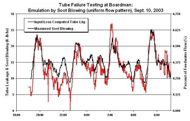
Input/Loss Method - Tube Failure Detection  Input/Loss has an ability to rapidly detect tube failures and their location within the Steam Generator, without direct instrumentation. By "location" implies the heat exchanger in which a tube has failed, and thus leaking to the combustion space; e.g., a tube failure in the Economizer, Reheater, etc. Rapid detection reduces damage, minimizes degraded heat rate, and minimizes repair time, thus saving million of dollars. Tube failures are detected through use of system stoichiometrics, in combination with an ability to correct effluent data through use of optimization procedures. A Stack H2O instrument is not required, nor is its presence a panacea. The location of the failure within a Steam Generator is determined through use of energy balances and iterative techniques - made possible only because of the integration between effluents and boiler efficiency. Further, the model also indicates how the stoichiometric mechanism of a tube failure has been identified. Effluent water concentration (at the Stack) may consist of many sources: water formed from the combustion of hydrocarbons; free water born by the fuel; moisture carried by combustion air including air leakage; heat exchanger tube leaks; water added at the point of combustion (e.g., steam used to atomize fuel); pollutant control processes resulting in the in-flow of water; and soot blowing. All such sources of water are addressed by Input/Loss Methods through system stoichiometrics or direct measurements and integrated through a high accuracy boiler efficiency ... in combination with an ability to correct COP parameters through ERR-CALC procedures. To date, the Tube Failure Model has successfully identified a number of tube failures at several installations. Indeed, its initial success at Portland General Electric's Boardman unit has lead to an aggressive testing program running from September 2003 through March 2004. This effort routed blow-down lines from the inlet heaters of all major heat exchangers to the combustion space. The blow-down flows were individually metered. Thus through selected blow-downs, proof-of-process testing demonstrated the predictability of the Tube Failure Model. In addition to this direct injection, testing involves emulating tube leakage using soot blowing steam: by simply declaring soot blowing flow to be an unknown and allowing the Engine to compute a "tube leakage", then comparing results. Results from the Boardman testing are spectacular, meeting all original objectives: -Detection sensitivity is demonstrated at the ±2,000 lbm/hr level (0.05% of feedwater flow). -Leak locations were successfully predicted in all five heat exchangers tested. -The thermal impact of tube leakage is a function of leakage location; as demonstrated by test, and assuming a 40,000 lbm/hr leakage, effects include: 1.0% ΔηB in boiler efficiency at the Economizer, varying to 0.5% at the Reheater. Before this testing such losses were unknown to the industry ... as tube leakage was under- appreciated. Comparisons to soot blowing flow are presented above as are the results from a direct injection. Bear in mind that a 2,000 lb/hr resolved tube leak is only 0.05% of feedwater flow at Boardman, this is well within typical data chatter associated with feedwater flow metering. However, Input/Loss system stoichiometrics are sufficiently sensitive to allow for such detection even at these low levels. View Video on the "Detection of Tube Leaks and Their Location Using the Input/Loss Methods" -> Read technical paper on the "Detection of Tube Leaks and Their Location Using Input/Loss Methods" -> |
||||||||||||
| Privacy | Contact Us © 2011 All Rights Reserved. Exergetic Systems, Inc. | ||||||||||||