![]() Emission
Spectral Radiometer/
Emission
Spectral Radiometer/

Fuel Flow Instrument (ESR-FF)
The ESR/FF Instrument is another example of a Directed Development
project. A rudimentary version of the Input/Loss Method required high accuracy
measurements of combustion effluents. Although the current Input/Loss Method
corrects effluent measurements using a discovered fuel parameter and statistical
methods (a non-direct method, see the Part IV paper), in the 1980s direct
measurements were required with laboratory-grade accuracy. No such instrument
was available, and certainly not available for a power plant environment such as
found at the Mohave Generating Station, site of much of the early effort. The
conditions at Mohave were indeed severe: summer-time temperatures could easily
exceed 122oF (50oC), with flue gas opacity greater than 25% through a 30 foot (9
meter) duct. Note that the US Environmental Protection Agency has never require
absolute accuracy of power plant pollutants, only relative. Faced with such
difficulties, and believing in the importance of Input/Loss to the coal-fired
industry, Exergetic Systems developed its own cross-stack instrument, the ESR/FF.
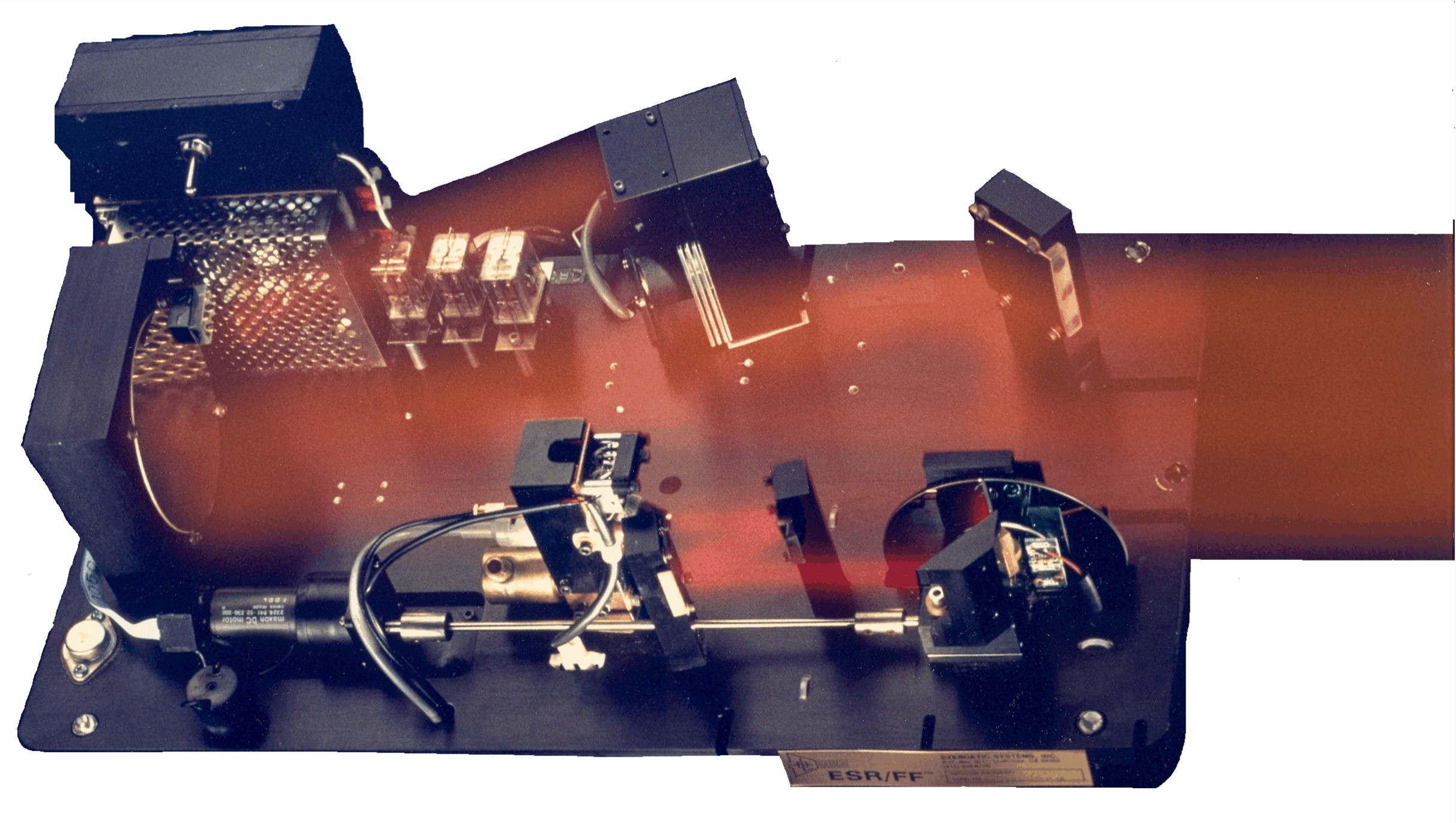
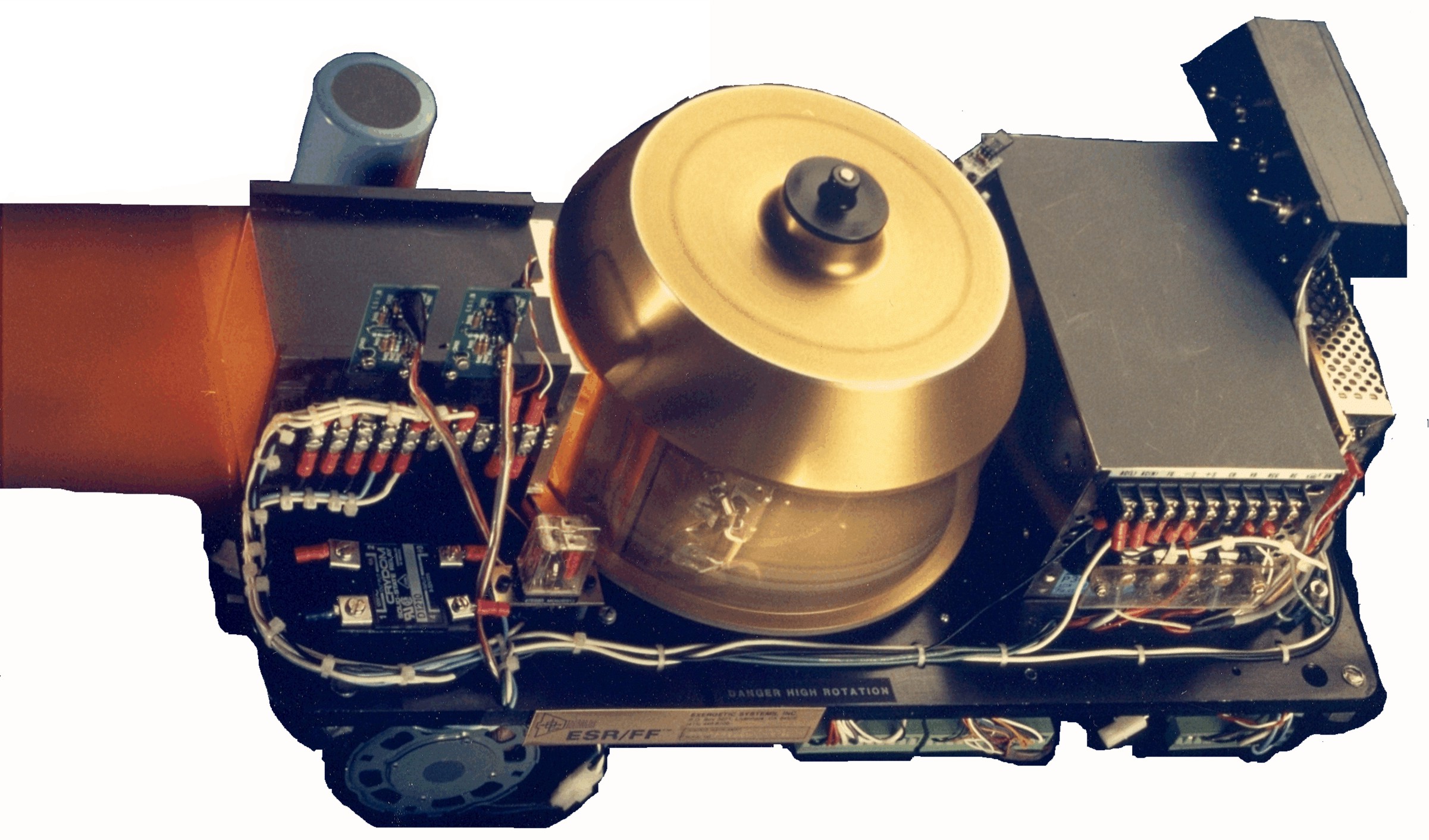
The ESR/FF Instrument was in-situ, consisting of a Detector Instrument and a
Source Instrument mounted on opposite sides of the flue duct. ESR/FF measured
with great accuracy (less than ±0.1% absolute resolution) the concentrations of
CO2 and H2O. Additionally, the concentrations of CO, SO2, SO3, NO and NO2 were
also detected, as was opacity. The first functionality of ESR/FF was its ability
to satisfy all EPA effluent requirements. Its second functionality was to
support the, then current, Input/Loss Method.
The Source Instrument housed an infrared (IR) source, its optics and
electronics. The IR source was a 1700o Kelvin graphite lamp used to deliver
adequate flux to the Detector Instrument given a highly sooted medium. The IR
beam was optically interrupted using a 2250 rpm shutter. Both Source and
Detector units were pressurized with ultra clean, dry air for the purpose of
eliminating moisture and contaminants from the instrument cavities. A valve body
provided interface between a flange and the instruments. The valve body
contained a sapphire window kept clean using a continuous air cone within which
a secondary stream of ionized air prevented static buildup from holding dirt
particles. The unit?s temperatures were controlled using thermoelectric coolers.
The Detector Instrument employed a lead-selenide detector, sensitive to
radiation between 1000 to 6000 nanometers and operating at -30oC using a
3-stage Peltier Cooler with a metering thermistor and pre-amplifier. Such
cooling was required to achieve maximum sensitivity and to guard against
detection of ambient temperature affects. Calibration assured that the source
lamp?s blackbody characteristics were preserved. All Detector unit optics were
gold coated. To achieve spectral absorption, the IR signal was passed through a
dispersive Continuous Variable Optical filter. The detector signal was routed
through coaxial cable and specially shielded circuit traces to a D/A Converter,
and then to a conditioned cabinet housing the Data Acquisition Interface
(motherboard) and Instrument Computer.
Directed Development leading to the ESR/FF resulted in installing eight systems,
the issuing of US Patents 5306209 and 5327356, and publishing critically
reviewed papers in Applied Optics (vol.35, no.3, pp.351-363) and in Applied
Spectroscopy (vol.47, no.4, pp.479-488). In 1995 the then owner of Exergetic
Systems, a subsidiary of San Diego Gas & Electric, was failing, cutting support.
Although since 1995 Exergetic Systems has been an employee-owned company, the
spirit which created ESR/FF continues.

© 2011 All Rights Reserved. Exergetic Systems, Inc.